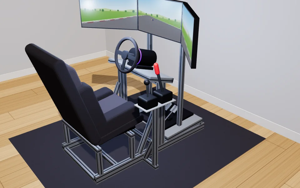
Why 40 x 80 under the seat and the wheel
The two base rails and the two wheel-deck posts are 40 x 80; everything else is 40 x 40. The reason is in RS PRO's profile datasheet: stood on its narrow face, 40 x 80 has a second moment of area of 70.07 cm⁴, against 9.18 cm⁴ for 40 x 40, so it bends about 7.6 times less under the same load. Laid flat it drops to 16.93 cm⁴, which is why the tool stands every 40 x 80 piece on edge, in the direction the wheel and your weight push.
The profile, cut by cut
Profile is ordered cut to length in millimetres, so the lengths are given that way, with inches alongside. Every cut is square; the braces meet the frame through angle brackets, so nothing needs a mitre.
| Length | Pieces | Where it goes |
|---|---|---|
| 1370 mm (53 7/8 in) | 2 | Base, left side rail; Base, right side rail |
| 657 mm (25 7/8 in) angled ends | 2 | Wheel deck, post, top cut to the deck angle |
| 560 mm (22 in) | 1 | Base, cross member |
| Length | Pieces | Where it goes |
|---|---|---|
| 1219 mm (48 in) | 2 | Screen stand, post |
| 640 mm (25 1/4 in) | 2 | Seat mount, bar across the rails |
| 624 mm (24 5/8 in) | 1 | Shifter, post |
| 601 mm (23 5/8 in) | 1 | Screen stand, bar across |
| 560 mm (22 in) | 5 | Base, cross member; Pedal deck, cross brace; Wheel deck, cross bar under the deck |
| 520 mm (20 1/2 in) | 2 | Screen stand, foot |
| 510 mm (20 1/8 in) | 2 | Pedal deck, stringer |
| 501 mm (19 3/4 in) angled ends | 2 | Wheel deck, brace |
| 290 mm (11 3/8 in) | 2 | Wheel deck, rail |
| 264 mm (10 3/8 in) angled ends | 1 | Shifter, brace |
| 221 mm (8 3/4 in) | 4 | Seat mount, riser |
| 180 mm (7 1/8 in) | 1 | Shifter, arm out from the base |
| 24 mm (1 in) | 2 | Pedal deck, post |
To cut it yourself from the 1, 2 and 3 m lengths suppliers stock, with a 3 mm saw kerf: the 40 x 80 comes out of 2 of 3 m (1371 mm left over), the 40 x 40 out of 5 of 3 m (2158 mm left over). A mitre saw with a blade for aluminium, clamped, and a file for the burrs is enough.
Brackets, T-nuts, bolts and caps
| Item | Quantity | How it is counted |
|---|---|---|
| Corner brackets for 40 mm profile, 8 mm slot | 90 | Two on each joint where a 40 mm face meets, four where the face is 80 mm. |
| Hinge or angle brackets | 6 | One at each angled end of the braces. |
| T-nuts for 8 mm slot, M8 | 210 | Two for each bracket, one for each plate fixing. |
| M8 button-head bolts with washers | 210 | One for each T-nut. |
| End caps, 40 x 80 mm | 4 | On every open end of 40 x 80. |
| End caps, 40 x 40 mm | 21 | On every open end of 40 x 40. |
Slide the T-nuts into the slots before you close a frame: a drop-in T-nut can go in later, but a slide-in one cannot once both ends of the slot are blocked. The seat's brackets or sliders bolt to the two seat bars with M8 bolts into T-nuts as well.
The plates and the gear
The wheel, pedal and shifter plates here are 6 mm aluminium, cut from the DXF files the tool writes, 4 holes for the wheel base, 6 for the pedals and 8 for the shifter and handbrake. Their fixings are slots over the profile, so each plate can slide a little before its M8 bolts are tightened into T-nuts. How the plates are drawn and cut covers the files, the hole patterns and the cutting; the bolts into your gear depend on its threads, so the shopping list leaves their size to you.
Heights to build to, for a 6 ft driver
| From the floor to | Height |
|---|---|
| The hip point | 481 mm (18 7/8 in) |
| Your heels on the pedal deck | 126 mm (5 in) |
| The wheel centre | 938 mm (36 7/8 in) |
| The middle of the screens | 1219 mm (48 in) |
| Your eyes | 1219 mm (48 in) |
Seat back 18 degrees from upright, wheel tilted 18 degrees, heels 684 mm (26 7/8 in) ahead of the hip point. Three 27 in screens at 873 mm (34 3/8 in) from the eyes fill 115 degrees across, with the side screens turned in 39 degrees; set the game's field of view to the same figures and the track keeps its true size.
Open this aluminum rig in the tool