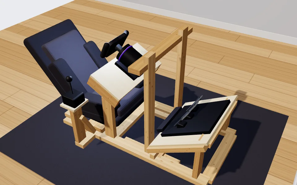
Three plates, one file each
| Plate | Size | Gear holes | Fixings to the frame |
|---|---|---|---|
| Wheel deck plate | 25 1/16 in x 11 7/16 in | 4 at 6.5 mm, slotted 1 3/16 in | 6 pilot holes |
| Pedal plate | 25 1/16 in x 20 1/16 in | 6 at 8.5 mm, slotted 1 3/16 in | 8 pilot holes |
| Shifter plate | 6 5/16 in x 5 1/2 in | 4 at 6.5 mm | 4 pilot holes |
The frame itself needs no CNC: every 2x4 piece is a straight cut, listed in the cut list. The plates are where a machine helps, because the gear bolts through them and the holes have to land within a millimetre or so of your hardware.
What is inside a DXF file
- DXF version R12, in plain text. It holds nothing but lines, arcs and circles, which keeps it readable by old and new CAD and CAM programs alike.
- Three layers. CUT_OUTLINE is the outside of the plate, with 12 mm corner radii. CUT_HOLES holds a circle for each round hole and two lines and two arcs for each slot. NOTES carries the plate's name and size and is not meant to be cut.
- Units in the header. Millimetres by default, or inches if you tick the option; the file says which in its $INSUNITS value, 4 for millimetres and 1 for inches, so a CAM program can scale it correctly.
- The origin at the lower left corner. The outline runs from 0,0, and the hole positions in the build plan are measured from the same corner, so a dimension on paper and a coordinate in the file agree.
On a CNC router
Set CUT_OUTLINE as an outside profile, so the cutter runs outside the line and the plate comes out at its drawn size, and CUT_HOLES as inside profiles. Leave a few holding tabs on the outline, or screw the sheet down outside the part, since a plate that breaks free in the last pass can be thrown by the cutter. The holes in this design are 6.5 mm and 8.5 mm; a hole smaller than your cutter has to be drilled instead, and the DXF still marks its centre.
By laser or waterjet, in aluminium
On a 40-series aluminium frame the tool can draw the plates for 6 mm aluminium instead. The fixings then become 8.5 mm slots that sit over the profile's slot, for M8 bolts into T-nuts, so a plate can slide a little before it is tightened. Send the millimetre files; a cutting service quotes from the outline length and the number of holes, which the README in the download lists for each plate.
By hand, with a drill and a jigsaw
Without a machine, cut each plate as a rectangle along a straightedge, round the corners with a jigsaw, and drill the gear holes through a paper template. The Pro build plan prints each plate's gear holes at full size, tiled over as many pages as it needs, with a 100 mm and a 4 in bar on every page to prove the printer did not scale it. Lay the template's middle line on a line drawn across the middle of the plate and its lower edge on the plate's back edge, centre-punch every cross and drill. For a slot, drill both ends and cut between the holes with the jigsaw.
Measure your gear before anything is cut
Sim Rig Designer stores no maker's bolt pattern. Every plate starts with an example (2 by 2 holes for the wheel base, 3 by 2 for the pedals), and the checks flag each plate as an example until you type your own A, B and D and tick it as measured. The slots run 1 3/16 in front to back, so the wheel base and the pedals can still slide a little to find the right reach once they are bolted down.
Open this rig and its plates in the tool